Homemade Cell Phone Signal Booster Circuit Diagram
BlogHomemade Cell Phone Signal Booster Circuit Diagram in this video we learn How to make simple signal booster device easy at home. its very simple easy and homemade project. in this circuit i use MPF102 IC. its
With just a few simple components and some know-how, you can put together a 4G mobile signal booster circuit that will ensure you stay connected wherever you go. Building your own mobile network booster requires just a few pieces: an amplifier, a power source, an antenna of the right size and frequency, a feeder cable, and mounting hardware.

Mobile Signal Booster using LM386 IC Circuit Diagram
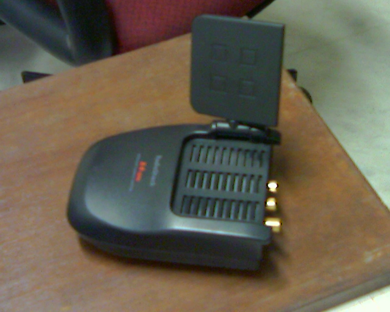
The amplified signal goes out of the VGA into a plate antenna which is located inside the building and transmits the signal to the cell phone. Step 2: Video Demonstarion This video above shows all the main components of the repeater, which is demonstrated using my own phone and a spectrum analyser, which has a small 'whip' antenna located right Understanding How the Mobile Signal Booster Circuit Works. Before diving into the construction of a mobile signal booster circuit, it's essential to grasp the underlying principles of its operation. This knowledge will empower you to make informed decisions during the design and troubleshooting phases. The circuit functions by amplifying the

A good signal strength define is maybe a stable 3 bar 2G signal, not a unstable signal strength jump up and down too often. Probably take a while for getting the right place. If you not very sure, just make it 7 round /turns at out door unit and 5 round /turns at indoor unit.
Homemade Mobile Signal Booster Circuit Diagram
Hi there in this video I'll be showing how to make a GSM booster at home using LM386 IC ,this is a 100% working circuit with very cheap components.Materials Circuit Diagram Working Explanation. In this Mobile Signal Booster, when you give the supply to the circuit, the input antenna captures the weak transmission surrounding your cell phone. And, then, it transferred the captured transmission to the non-inverting input pin of the connected opamp IC.
